Field signals
Digital status, relay control, voltage or current input, and analog output.
Connect digital and analog field signals to PLCs, SCADA systems, and edge controllers. Choose from compact digital I/O, mixed I/O with relay outputs, and high-density DI, AI, or AO modules.

Digital status, relay control, voltage or current input, and analog output.
PLCs, SCADA systems, and edge controllers with a compatible serial interface and register map.
RS485 Modbus RTU across the family; additional interfaces and ASCII on selected models.
DIN-rail modules for control panels. Confirm supply voltage and environmental limits by model.
A Y301 module sits between field signals or loads and the PLC, SCADA system, or edge controller that reads and writes its registers.
Signal sideConnect compatible inputs, relay loads, or analog outputs for the selected model.
Module roleThe module exposes field states and values to the host; it does not replace the controller.
Host sideMatch the interface, protocol mode, baud rate, address, and register map.
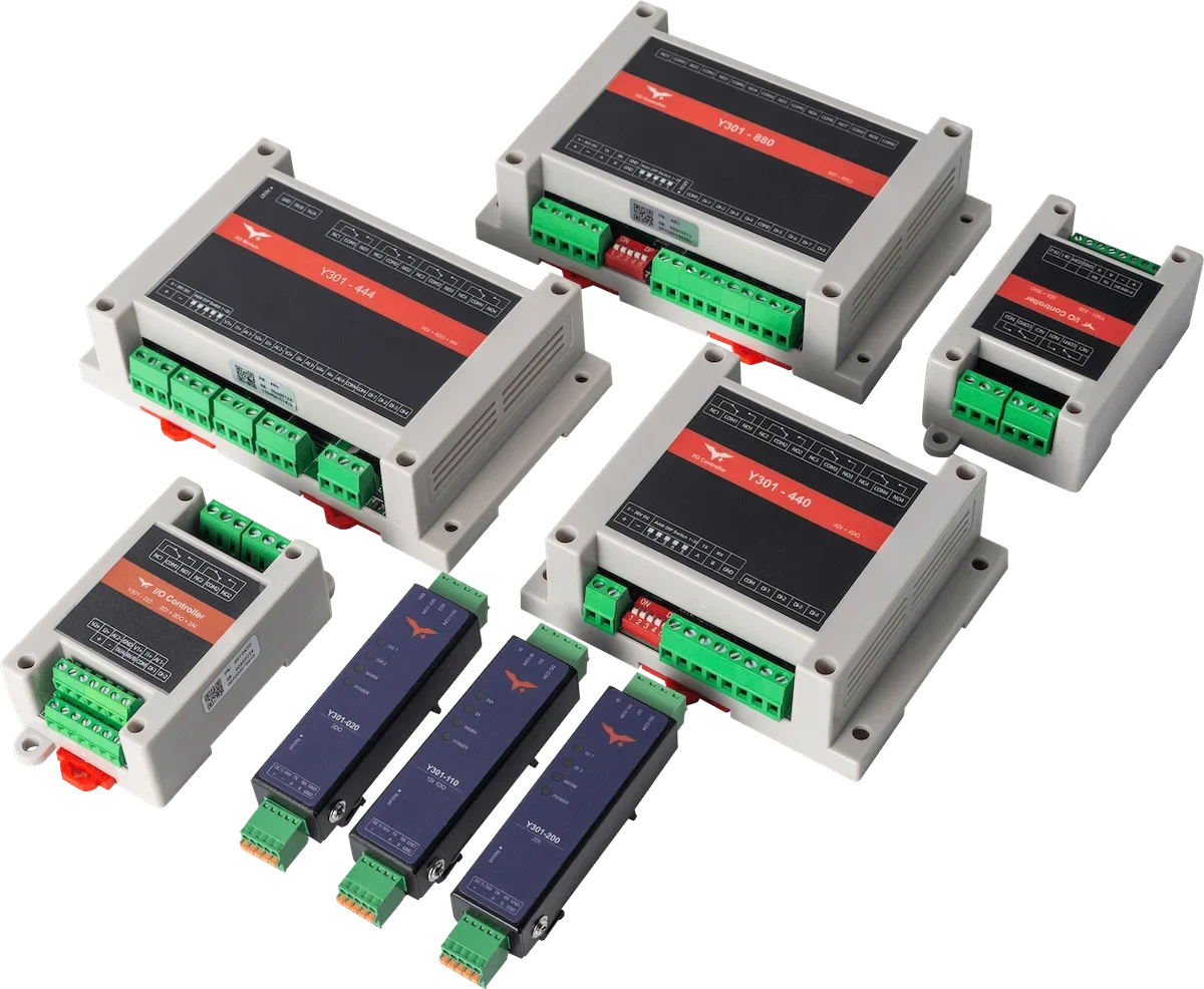
MiniLink, ControlLink, and FlexPoint organize the Y301 range by I/O combination and project task.

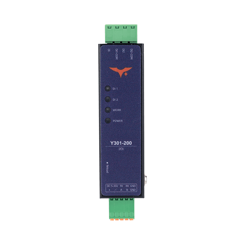
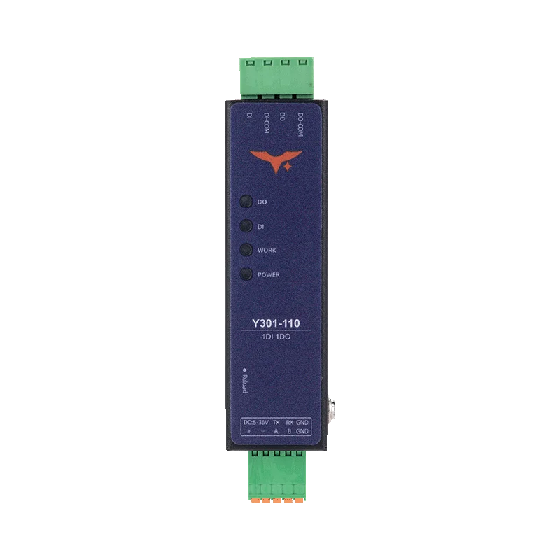
Compact one- or two-channel digital I/O for status monitoring and relay control.
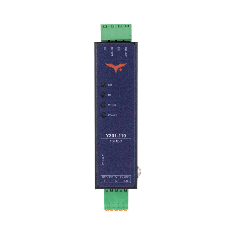
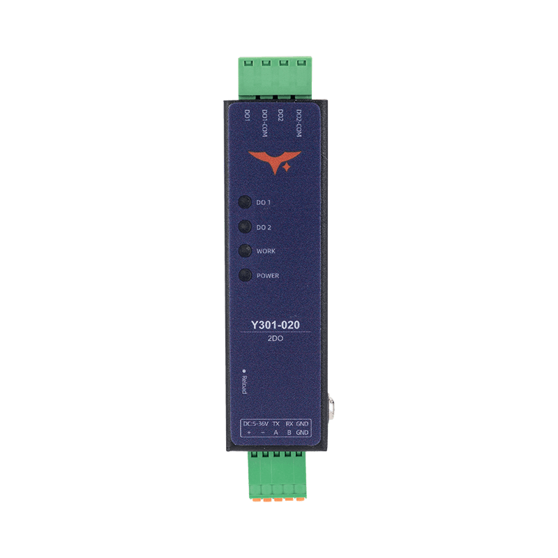
Y301-110 · Y301-200 · Y301-020
View MiniLink Models
Combined digital input and relay output, with analog input and local rules on selected models.
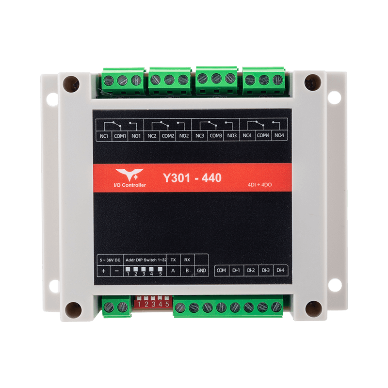
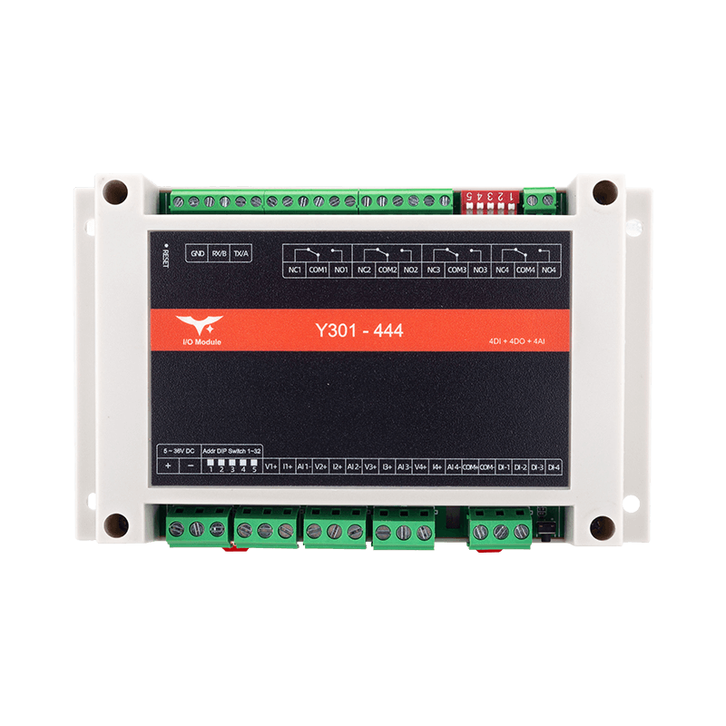
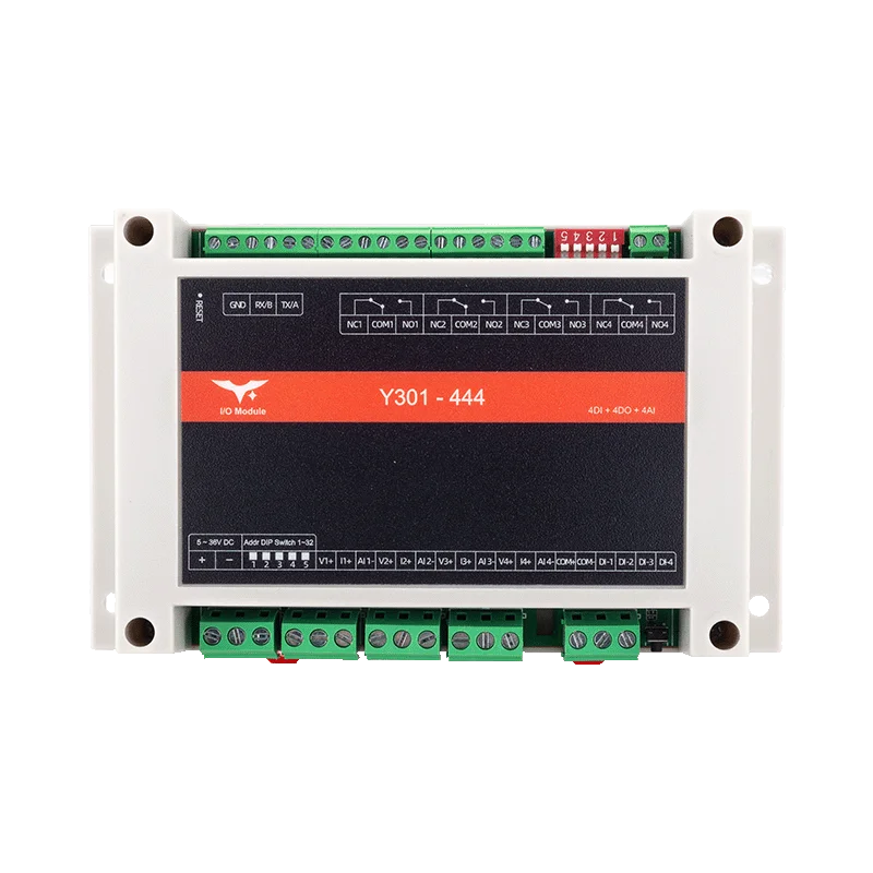
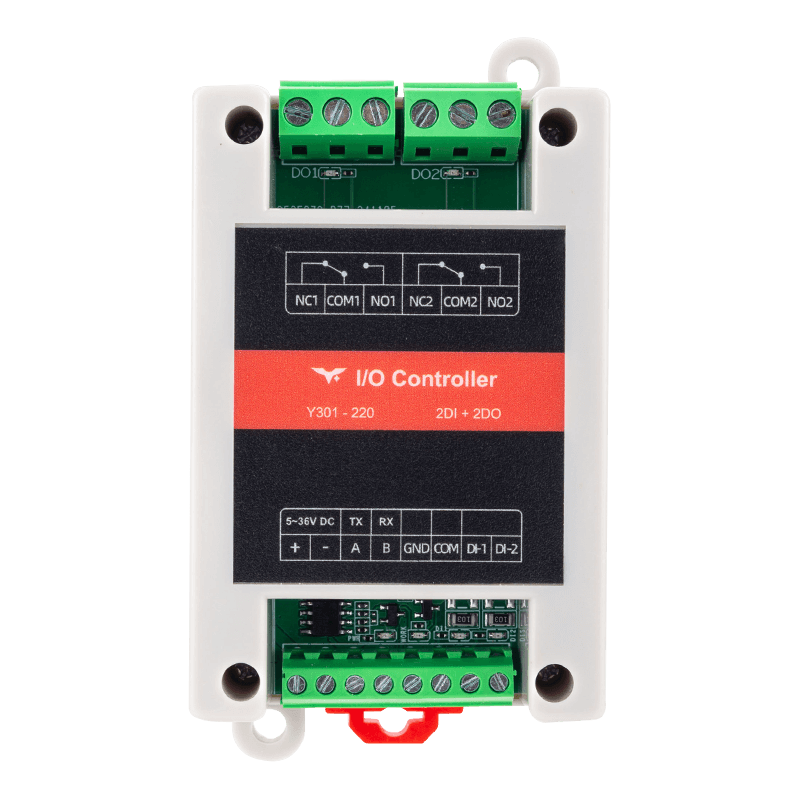
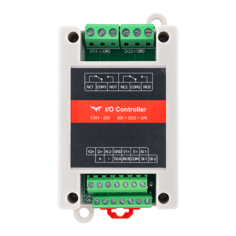
Y301-220 · Y301-222 · Y301-440 · Y301-444 · Y301-880
View ControlLink Models
Dedicated DI, AI, or AO modules for higher channel counts and signal-specific expansion.
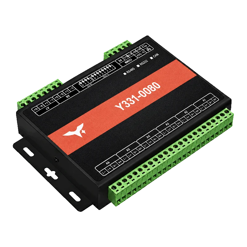
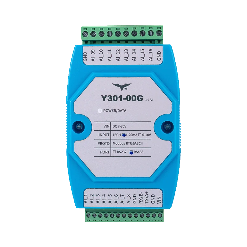
Y301-600 · Y301-800 · Y301-G00 · Y301-006 · Y301-008 · Y301-00G · Y301-0004 · Y301-0006 · Y301-0008
View FlexPoint ModelsUse these three wiring patterns to identify the right product family. Final selection still depends on signal range, load, interface, supply, and installation conditions.
Scan the compact model list, then open the detailed comparison for interface and electrical limits before final design or ordering.
Compact one- or two-channel digital I/O for status monitoring and relay control.
| Model | I/O | Power | Interface / protocol | Signal or load boundary | Best for | Action |
|---|---|---|---|---|---|---|
| Y301-110 | 1 DI + 1 relay DO | 5–36 VDC | RS485; optional RS232 / TTL · Modbus RTU | SPDT relay · 277 VAC 10 A / 28 VDC 10 A | One status input and one relay-control point | |
| Y301-200 | 2 DI | 5–36 VDC | RS485; optional RS232 / TTL · Modbus RTU | Dry / wet contact inputs · opto-isolated | Two-channel status monitoring | |
| Y301-020 | 2 relay DO | 5–36 VDC | RS485; optional RS232 / TTL · Modbus RTU | SPDT relays · 277 VAC 10 A / 28 VDC 10 A | Two relay-control points |
Combined digital input and relay output, with analog input and local rules on selected models.
| Model | I/O | Power | Interface / protocol | Signal or load boundary | Best for | Action |
|---|---|---|---|---|---|---|
| Y301-220 | 2 DI + 2 relay DO | 5–36 VDC | RS485; optional RS232 / TTL · Modbus RTU | 10 A relays · up to 4 local rules | Compact monitoring and relay control | |
| Y301-222 | 2 DI + 2 relay DO + 2 AI | 5–36 VDC | RS485; optional RS232 / TTL · Modbus RTU | 0–10 V / 4–20 mA AI · 16-bit · up to 4 rules | Mixed digital and sensor monitoring | |
| Y301-440 | 4 DI + 4 relay DO | 5–36 VDC | RS485; optional RS232 / TTL · Modbus RTU | 10 A relays · up to 8 local rules | Four-point monitoring and control | |
| Y301-444 | 4 DI + 4 relay DO + 4 AI | 5–36 VDC | RS485; optional RS232 / TTL · Modbus RTU | 0–10 V / 0–5 V / 4–20 mA AI · up to 8 rules | Mixed four-channel monitoring and control | |
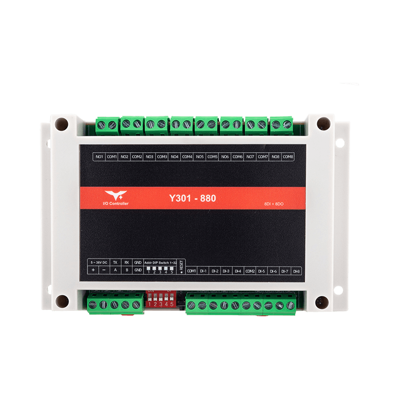
| Y301-880 | 8 DI + 8 relay DO | 5–36 VDC | RS485; optional RS232 / TTL · Modbus RTU | 10 A relays · up to 16 local rules | Higher-density digital monitoring and control |
Dedicated DI, AI, or AO modules for higher channel counts and signal-specific expansion.
| Model | I/O | Power | Interface / protocol | Signal or load boundary | Best for | Action |
|---|---|---|---|---|---|---|
| Y301-600 | 6 DI | 7–30 VDC | RS485 / RS232 · Modbus RTU / ASCII | Opto-isolated DI · 3.3–24 VDC active input | Six digital status points | |
| Y301-800 | 8 DI | 7–30 VDC | RS485 / RS232 · Modbus RTU / ASCII | Opto-isolated DI · 3.3–24 VDC active input | Eight digital status points | |
| Y301-G00 | 16 DI | 7–30 VDC | RS485 / RS232 · Modbus RTU / ASCII | Opto-isolated DI · 3.3–24 VDC active input | Sixteen digital status points | |
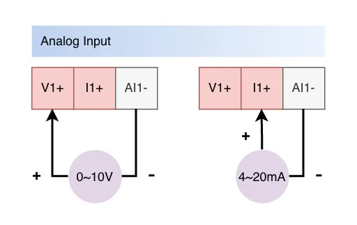
| Y301-006 | 6 AI | 7–30 VDC | RS485 / RS232 · Modbus RTU / ASCII | 0–10 V / 4–20 mA · 12-bit · ±0.5% FS | Six analog measurement points | |
| Y301-008 | 8 AI | 7–30 VDC | RS485 / RS232 · Modbus RTU / ASCII | 0–10 V / 4–20 mA · 12-bit · ±0.5% FS | Eight analog measurement points | |
| Y301-00G | 16 AI | 7–30 VDC | RS485 / RS232 · Modbus RTU / ASCII | 0–10 V / 4–20 mA · 12-bit · ±0.5% FS | Sixteen analog measurement points | |
| Y301-0004 | 4 AO | 12–30 VDC | Isolated RS485; optional RS232 · RTU / ASCII | 0–10 V / 4–20 mA · 14-bit · ±0.1% FS | Four analog setpoint outputs | |
| Y301-0006 | 6 AO | 12–30 VDC | Isolated RS485; optional RS232 · RTU / ASCII | 0–10 V / 4–20 mA · 14-bit · ±0.1% FS | Six analog setpoint outputs | |
| Y301-0008 | 8 AO | 12–30 VDC | Isolated RS485; optional RS232 · RTU / ASCII | 0–10 V / 4–20 mA · 14-bit · ±0.1% FS | Eight analog setpoint outputs |
Need help choosing? Get a model recommendation.
The correct model depends on the signal, electrical load, host connection, power, environment, and local-control requirement.
Identify each DI, relay DO, AI, or AO point and whether the signal is digital, voltage, or current.
Count the required points and allow only the project margin you can justify.
Confirm analog range or relay operating voltage, steady current, inrush current, and load type.
Confirm RS485, RS232, or TTL availability and the required Modbus mode for the selected model.
Check supply voltage, temperature, humidity, enclosure, wiring, and installation clearance.
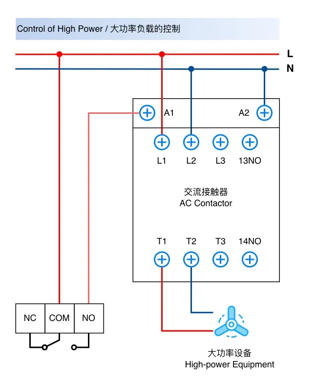
Confirm whether local rules, retention, converters, termination, protection, or external contactors are required.
Questions that change model selection. Check the product family, signal type, communication option, load, and required documents before final selection.
Start with MiniLink for compact one- or two-channel digital I/O, ControlLink for combined digital input and relay output with analog input on selected models, and FlexPoint for dedicated higher-channel-count DI, AI, or AO expansion. Then compare channel count and model-specific electrical limits.
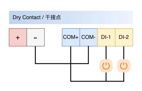
Use DI for discrete status signals, relay DO for on/off load control, AI for supported voltage or current measurements, and AO for supported voltage or current setpoints. Confirm signal range, common wiring, isolation, accuracy, and load requirements in the selected model specification.
RS485 Modbus RTU is available across the documented Y301 family. RS232, TTL, and Modbus ASCII are available only on selected models. Match the host interface, protocol mode, baud rate, address, and register map to the selected model.
Do not select a relay from steady current alone. Check operating voltage, inrush current, switching frequency, and load type. Y301-110 and Y301-020 relay contacts are rated 277 VAC 10 A or 28 VDC 10 A under the designated specification, but the application may still require protection or an external contactor.
Share the I/O type and channel count, signal range or load, host interface and protocol, supply voltage, installation environment, and any local rule requirement. Submit the conditions you know; missing details can be confirmed later.
Open the detailed comparison above and follow the selected model specification for electrical and mechanical limits. Use the linked technical reference for wiring, configuration, communication settings, and register information.
Share the I/O and project conditions you know. We will use them to narrow the product family and model.