Wireless I/O Modules · Y401 / Y402 / Y403

Replace Long Control Cables with Wireless I/O

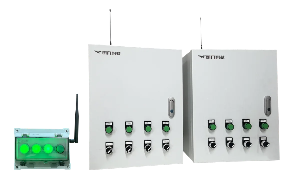
Send passive dry-contact or NPN open-collector states to remote SPDT relay outputs over a private LoRa link. Choose Y401, Y402 or Y403 by control relationship and I/O count, then confirm radio range for the actual site.

For auxiliary control and signalling. Emergency-stop, life-safety and hard-real-time circuits must stay on their own independently certified system.

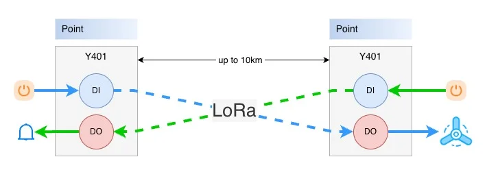
Digital input flowing to a remote digital outputTwo wireless I/O nodes transfer digital input states over a private wireless link to corresponding digital outputs, with an open-area range option up to 10 kilometres; actual range depends on the model, antenna and site conditions.UP TO 10 KM*OPEN-AREA RANGE OPTIONFIELD INPUTDI INPUTSTATE INREMOTE OUTPUTDO OUTPUTSTATE OUT
Direct I/O
state linkage
DI over
private LoRa
SPDT relay
to load circuit

Local control without a long signal cable

How Wireless I/O Signal Transfer Works

A field input changes at one node, the Y40 link carries that state over LoRa, and a relay contact changes at the linked node or nodes.

Input state in. Linked relay state out.The selected topology determines which node or nodes respond.
  1. 01 · Field input

    Read the field signal

    Connect a passive dry contact or NPN open-collector output to DI. Never apply voltage directly to DI.

  2. 02 · Radio link

    Transmit the state

    Factory-paired or commissioned modules exchange the I/O state over a private 398–525 MHz LoRa link.

  3. 03 · Relay output

    Switch the remote circuit

    The linked SPDT relay changes state. Use an external supply and a suitable contactor when the load requires one.

Step 1 · choose a topology

Choose the Control Relationship

Start with the relationship between locations: two points, one master with several slaves, or multiple equal nodes. This determines the Y401, Y402 or Y403 series before I/O count enters the decision.

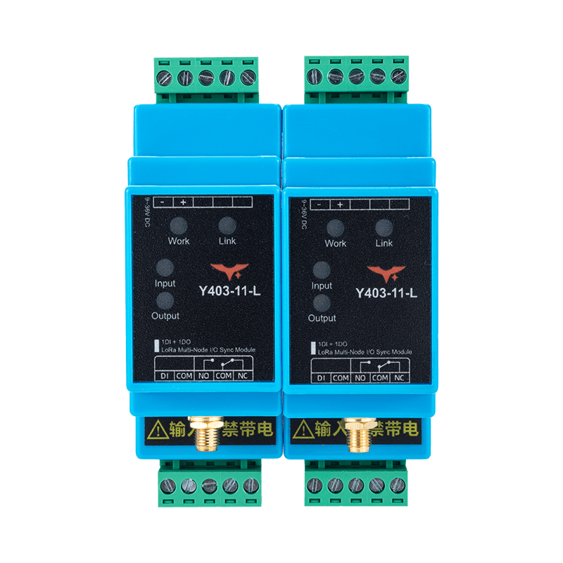
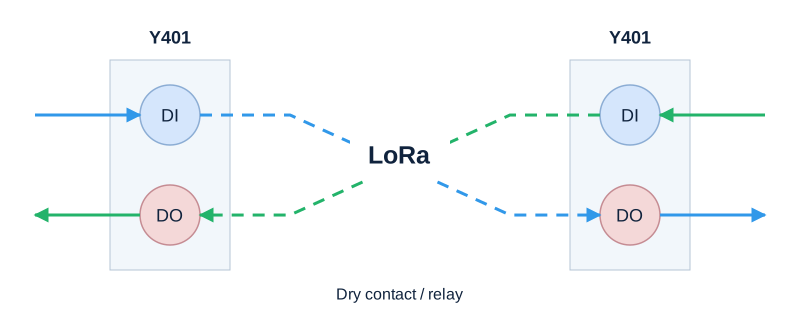
Y401 point-to-point LoRa I/O control relationship between two locations
Y401

Two locations

Corresponding DI channels at either node drive the remote node relay outputs.

Typical fitA single control-cable replacement between two points.
View Y401 models
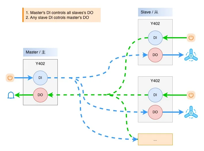
Y402 one-to-many LoRa I/O control relationship between one master and multiple slaves
Y402

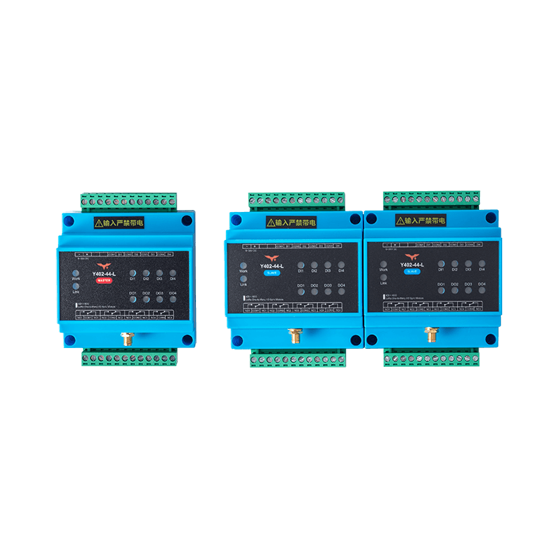
One master, multiple slaves

Master inputs drive matching outputs at all slaves; slave inputs can drive the matching master output.

Typical fitOne controller operating several remote points with return signalling.
View Y402 models
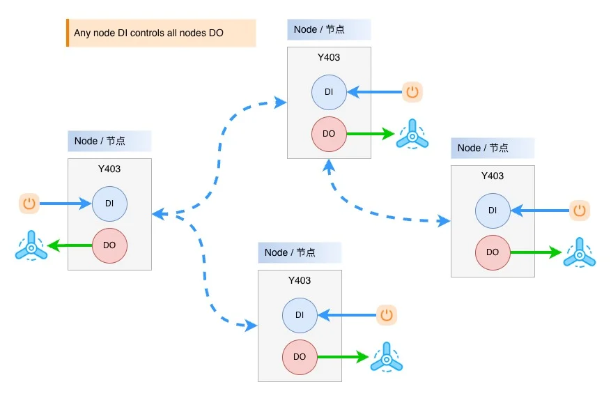
Y403 multi-node LoRa I/O linkage where any node input controls every node output
Y403

Multiple equal nodes

Any closed node input energizes all linked outputs, including the local output.

Typical fitMany trigger points that must activate every linked alarm or relay point.
View Y403 models
Not sure which relationship fits your site?Send the number of locations, I/O points, distance and intended load.
Request a Site Review

Common starting points

Typical Wireless I/O Applications

These examples show the signal relationship, not a finished-system design. Safety, load and compliance details always depend on your application.

Start with Y401 or Y402

Access-Control Signal Extension

Pass a dry-contact status or control signal between access-control equipment and a remote relay point when running a new cable is impractical.

Keep door hardware, fail-safe/fail-secure logic, fire release and code compliance inside the approved access-control design.

Start with Y403

Multi-Point Linkage Alarm

Connect distributed dry-contact triggers so an event at any node energizes every linked relay output for local alarm or auxiliary notification.

Use a dedicated safety or life-safety system where regulations or a risk assessment require one.

Start with Y401 or Y402

Remote Wireless Equipment Control

Send an approved control contact to a remote relay or suitably rated contactor for pumps, fans, gates or other field equipment.

Specify load switching, interlocks and feedback separately; the relay contact itself does not supply load voltage.
Step 2 · select the I/O count

Select a Wireless I/O Model

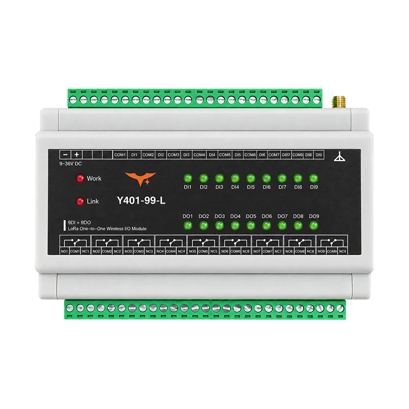
Start with the series that matches the control relationship, then select the input and output count required at each location. All current models share 9–36 VDC power, 35 mm DIN-rail mounting and SPDT dry-contact relay outputs.

01

Choose the seriesMatch the control relationship.

02

Choose the I/O countMatch the signals at each node.

03

Review the specificationConfirm wiring, radio and site conditions.

Y4013 models

Point-to-Point Wireless I/O

A factory-paired two-node link mirrors corresponding input channels to relay outputs in both directions.

Y4023 models

One-to-Many Wireless I/O

One master distributes matching input states to one or more slave nodes, while slave inputs can return a signal to the master.

Y4031 model

Multi-Node Linkage

When any linked node input closes, every node relay output energizes; outputs reset after all linked inputs open.

Information needed for selection

Describe the Site Before Choosing a Model

A short, specific site description is usually enough to pin down the topology and flag the details that still need checking.

  1. Control logic

    • Control relationshipTwo points, one-to-many or all-node linkage
    • I/O countDry-contact inputs and relay outputs at each location
  2. Installation

    • Radio pathDistance, obstructions, enclosure material and antenna location
    • Field powerAvailable 9–36 VDC supply and backup-power requirement
  3. Electrical behavior

    • LoadVoltage, current, inductive characteristics and required contactor
    • Required fail stateExpected behavior after power or wireless-link loss

Source documents

Manual and Model Specifications

Use the shared manual for wiring, pairing and commissioning, then check electrical and mechanical details in the selected model's specification.

Shared manualY401 / Y402 / Y403 User ManualWiring, pairing and commissioning guidanceOpen manual
Y401, Y402 and Y403 model specification documents
SeriesModelTopology / I/OAction
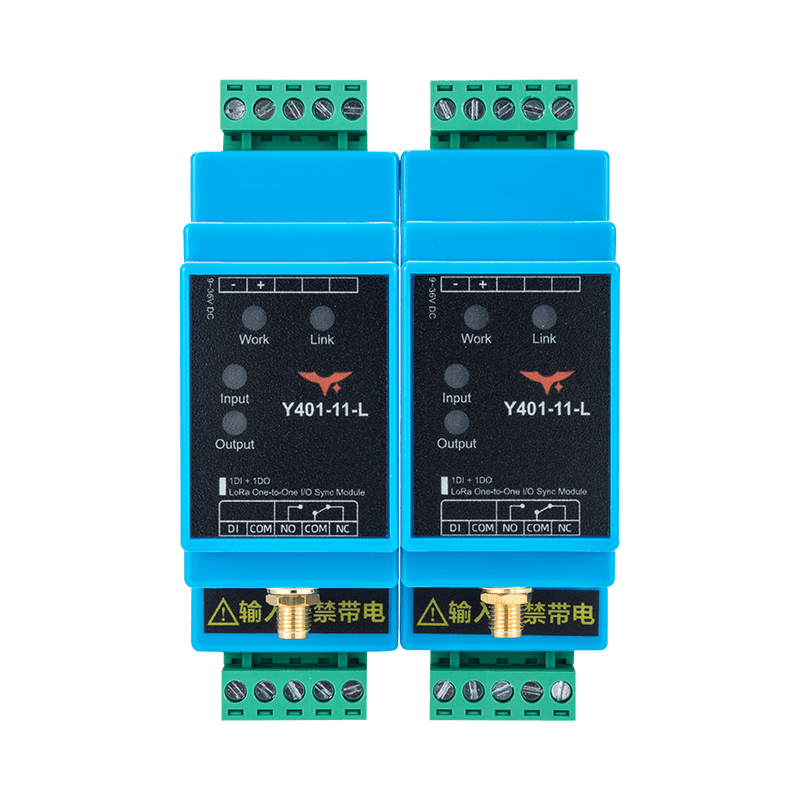
Y401SeriesY401-11-L1DI + 1DO per node · Point-to-pointOpen specification
Y401-22-L2DI + 2DO per node · Point-to-pointOpen specification
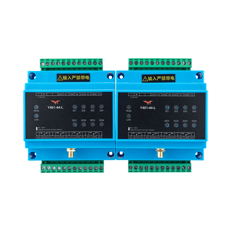
Y401-44-L4DI + 4DO per node · Point-to-pointOpen specification
Y402SeriesY402-11-L1DI + 1DO per node · One-to-manyOpen specification
Y402-44-L4DI + 4DO per node · One-to-manyOpen specification
Y402-4411-L1-channel master / 4-channel slave · One-to-four mappingOpen specification
Y403SeriesY403-11-L1DI + 1DO per node · Multi-node linkageOpen specification

Specifications include electrical and mechanical details for the selected model.

Selection questions

FAQ

These answers cover the current Y401, Y402 and Y403 family. For installation, the selected model's specification still governs.

What does a Wireless I/O Module do?

It reads a passive dry-contact or NPN open-collector input at one location and changes a linked relay output at another location over a private LoRa radio link. What exactly changes depends on whether you choose Y401, Y402 or Y403.

Which topology should I choose?

Choose Y401 for a two-location point-to-point link, Y402 for one master and multiple slave locations, and Y403 when any node input must activate all linked node outputs.

What input signals can connect to DI?

The digital inputs accept passive dry contacts or NPN open-collector signals. Never apply voltage to a DI terminal. Confirm the field-device output type before wiring.

What can the relay output switch?

The output is an SPDT dry-contact relay rated up to AC 277 V 5 A or DC 28 V 5 A. For high-power, motor or inductive loads, add a suitably rated contactor and surge suppression. The relay contact does not generate output voltage.

Can wireless I/O replace an emergency-stop or life-safety circuit?

No. Do not use this wireless link as the only emergency-stop, personnel-safety, life-safety or hard-real-time control path. Keep required safety functions on an independently designed and approved system.

Model selection / site review

Send Your Site and I/O Requirements

Share your topology, I/O count and site conditions. We'll recommend a starting model and identify any details still needed.